Sunday, July 14, 2013

Completed Hull

I completed the hull Last October. Before I took it out I had to make a few additions to it.


First I had to reinforce the transom with a continuation of the inwale.. I also glued a sheet of 9mm ply to the inside of the transom to take the screws holding the transon pintles and gudgeon for hanging the rudder. The plans called for a 6mm ply transom. I doubled mine to 12 and then added another 9mm. I think this will be thick enough to take the 10g self tappers going into the transom.


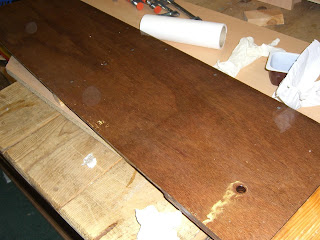
The thwart was made from threesheets of 6mm ply laminated. There is a cut-out section on the lower sheet to allow for where the thwart will sit over the side bench lids. I hope I never have to take off those lids!


The oarlock reinforcements for the gunwales were made from peices of douglas fir and shaped to fit under the inwale. They were glued and screwed in place.

After that it was pretty much finished.


I epoxy coated the entire hull again, inside and out and washed off the amine blush. This gave the epoxy an opaque look and I would reconsider doing this again. It did fade a bit after a few months in the garage as it boat dried.


Thursday, July 4, 2013

Foredeck, Mast Support, Samson post and Breasthook

The forward deck was also made from imagination. There are limited plans so you are given a lot of leeway as to how you would like the boat to look. The hard part about this was deciding how high up in the hull to put the foredeck and whether it should abut the mast. Also the angle of the foredeck and whether it would drain naturally towards the cockpit. I decided to go for a large foredeck with the mast stepped off the deck and not the bottom of the hull. Naturally I had to trim the mast to allow for this. It was also necessary to decide how the samson post would come up through the deck and how the bowsprit would be attached to the samson post.


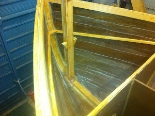
First the forward frame was reduced to the correct height and filletted in place. A frame stiffener was also added at the top.


Some deck supports were glued and screwed onto the hull.


A mast support was necessary under the foredeck and this was centered
with a string running the length of the hull. The mast support was made from a section of the mast that was not used.


The mast step was epoxied into position....


...and a longitudional support of 9mm ply put between it and the forward frame.
A hatch hole was put in place but in retrospect, I shouldn't have bothered. I put it there to allow me to get my hands in when gluing the deck in position and attaching hardware to the underside of the deck. Perhaps it will have its use in the future.


The samson post was glued into position with epoxy and some deck supports were screwed onto it. The position of the samson post was checked several times as the deck would be lowered onto the supports while the samson post passed through it. there would not be much room for error.


The deck was cut out. To get the shape right, I laid a piece of ply over the front of the boat and then crawled into the boat and with a pencil taped to a long stick I traced out the shape onto the underside of the ply. It was then cut to shape and fit fairly well after a small amount of trimming.


Of course I couldn't have a flat piece of ply just ending without some trim so I used three strips of 6mm thick Douglas Fir to make a curved trim/edge for the foredeck. Two pieces were laminated together first and held in the curve with small cargo straps. To get the correct curve I glued them and clamped them against the foredeck curve so that they would take the curve. I used cargo straps to take some of the pressure while they were curing. The above photo shows them after the clamps were removed but I kept the tension with the straps until the entire piece was glued to the foredeck.

Next, the two laminated strips were glued to the foredeck. This was accomplished by jamming the laminate up against the trailing edge of the foredeck. I glued it in position on a flat piece of melamine covered wood and used plenty of packing tape to prevent glue sticking to the upper edge of the laminate. The whole lot was in an upside-down orientation while being glued. The above photo shows them before gluing.


After the first two laminated layers of Douglas Fir were glued to the foredeck, I glued the next layer up against them. This layer was positioned aft of the other two layers and allowed all three layers to have a better grip on the foredeck. The photo above shows the entire shebang jammed between the gunwales and hull of the boat for tension..


The laminated 6mm strips were then filleted to the underside of the foredeck. the above photo shows this and also shows the foredeck reinforced with another layer of 6mm ply which was epoxied to the underside - just in case too many people decide to stand on the foredeck....


This photo shows the foredeck just before placement onto the boat. The edges of the foredeck have been masked off, the underside has been painted out similar to the side decks with four coats of primer and PreKote. The fore buoyancy compartment has also been painted out. The excess foredeck trim was removed and shaped before the foredeck was glued, filleted and taped into position....


...As shown here.


The mast step was placed.....


...with a 1 Euro coin epoxied into it.


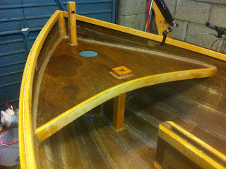
The samson post was also filleted into position and the breast hook glued and screwed to the gunwales.


A small piece of trim was used to tidy up the breast hook and complement the foredeck curve. The support for the bowsprit glued into the samson post with a tenon joint and also bolted down to the breast hook. The two forestays will be attached to the bowsprit so this needs to be well-held to the hull.


The finished result.

Side benches and buoyancy tanks

There are basic plans for side benches with this boat and the plans call for inflatable buoyancy bags which are placed under the benches. The plans do allow for tanks to be created but you have to guess where to put everything to make them. I chose to just have two side tanks and removed the rear bench as no-one would ever be sitting on it given that this is a sailing dinghy.


The frames were made of douglar fir and were epoxied to the hull and screwed through from the outside.


After the vertical component was attached, the tops of the frames were masked off so that the buoyancy tanks coule be painted out.


The bouyancy tank lids which were also the side benches, were reinforced on the underneath with 6.. ply epoxied  to them. The edges were masked off for gluing and also the strips which would sit on the horizontal frames.


The tanks were primed with two coats of International yacht primer and then had two coats of International PreKote. I didn't bother putting a Toplac coat on. Four coats plus the original epoxy coat on the wood should be enough.


The lids were epoxied onto the frames and held down for 24 hours with 25kgs distributed on each side. I had a look in the tanks to see if the epoxy was running. I made it fairly thick.


The lids were also filletted and taped at the edges.

Friday, September 21, 2012

Bilge runners and Skeg


Bilge runners were made from 25x25 Douglas Fir. They were glued to the hull and screwed from the inside. This was fairly hard and the wife was sent under the boat with an electric screwdriver to drive the screws through while I pressed down on the runners from the outside. You can see the amount of curve.


The runners were held down by cargo straps at the aft end of the boat.


For the end towards the bow, the curve is so severe that I had to use more bilge runner than would be left at the end of the process. I used the extra length of runner for leverage to hold down the runner where it was glued. You can see in the photo, I have put packing tape where the runner will eventually end. I screwed through the hull into the extra section of runner and filled the holes when this part of the runner was removed. To keep the correct twist in the runner and keep it flat against the hull I attached a clamp and applied torque by twisting it downwards and attaching it to a heavy floor jack with a cargo strap. 


After it all cured I cut away the excess runner and tidied up the edge. The ends were then tapered down.


The outer stem was made of five strips of 25x5mm Douglas Fir. I soaked and heated it as before and put it on a jig for a few days to get it to keep its shape as much as possible before laminating it and glueing it to the hull in one go. I could have laminated it in advance like the inner stem but I wasn't sure that my outer curve matched that in the plans so I just put thickened epoxy between the layers and started screwing them to the bow starting frmo the top end and working back towards the centreboard slot. Trying to keep it all straight was the hardest part. At one stage I had to hang out of the garage door mechanism with one hand whle standing with one foot on a ladder and another foot on the stem pressing it down into the curve.Then with one hand I drilled a pilot hole for the 50x5mm SS screws, swapped screwdrivers and screwed in the screws whiel trying not to fall off the stem of the boat. It wasn't easy to do this and watch "LA Confidential" on TV at the same time I can tell you!


A bevel was cut into the end of the stem to match up with the stem just forward of the centreboard slot.


The skeg was laminated from 3 peices of 6mm marine ply. The plans called for a 12mm skeg but this looked too thin when I made it so I laminated another layer to bring it to 18 which seemed more solid. 


The shaped skeg was glued and screwed through from the inside. Some cargo straps were used to keep it in position while this was going on.
  

The skeg supports were made from 25x25mm Douglas Fir. They were first attached at the forward end of the skeg with epoxy and screwed through from the inside as well. Excess 25x25 was used to allow a heavy weight to be placed on them for leverage to allow them to make the curve on the hull.


At the other end, another weight was placed to help them go around the curve of the hull.


Finished result at the back of the boat. A lot of epoxy to be scraped away and sanded later.


The other end was trimmed away, flush with the skeg.


Some packing tape was used to keep epoxy off the hull.


Centreboard slot runners/reinforcement were joined to the stem........


...and to the skeg reinforcements.

Monday, July 9, 2012

Centreboard and case

The centreboard is made from two peices of 9mm ply sandwiched together and it pivots on a 10mm stainless steel bolt. Here are some photos of the construction of the centreboard case and central frame.


Two halves of the centreboard case with the 25x50 mm frames. The sheets were sandwiched onto 25x50 ends as well.


A 9mm reinforcement section was added where the pivot bolt hole would be drilled.


Inside was coated with 5 coats of neat epoxy.


.....not forgetting the inside of the pivot bolt hole.


Two Halves were then joined together


squeezing out the glue, but not all of it.


Meanwhile the two sheets of 9mm ply for the centreboard were prepared.


Added on a section at the end of the centreboard to bring it up to the correct length.


Tried it out to make sure it all worked.


Then lined up the case on the hull to cut out the hole.


Pre-drilled some holes for 4x25 screws to hold it to the hull.


Put a bed of thickened epoxy around the hole.


I scored the bottom of the case frame and coated with neat epoxy.


Epoxy fillet was rounded off at the bottom of the case. Excess glue scraped away.


Before it cured, I rigged up something to keep it straight and upright.


25x50mm frames were inserted between the hull and case for the thwart and the central frame was put in. I may have made the hole in the frame too big but sure I'm not getting paid to do this!